3) There are many components happening in this lab. In order to find the time the cart travels one meter, our theory is to relate the tangential acceleration of the metal disk is equal to the acceleration of the cart. Let's first look at the metal disk. As the metal disk is rotating from the pull of the cart, the metal disk is experiencing two different types of torques. The first torque is the tension force from the cart. The second torque the metal disk will be experiencing is frictional torque. We will sum these torques to equal the moment of inertia of the disk and the angular acceleration. Instead of the string applying torque on the outer rim of the disk, it will be applying torque in the inner radius of the disk. Since the angular acceleration is the same all around the disk, linear acceleration will vary in different points of the radius. We will convert the angular acceleration to the tangential acceleration on the point of the inner radius and find the time it takes for the cart to travel one meter using linear kinematics for the cart. Here is an illustration to find the angular acceleration.

4) We first have to find a way to measure the frictional torque before we calculate the angular acceleration. In this lab, we did a video capture of the metal disk spinning until it stops.
 While the disk is spinning until it stops, the only torque applying to the disk is frictional torque. There's a piece of masking tape applied on the outer rim of the disk. We recorded the rotational motion in slow speed from a video recording phone. Then we uploaded the video on Logger Pro and applied the point on the masking tape each frame until the rotational motion is at rest. The graph it gives us will determine the slope of the angular velocity. That slope is the angular acceleration of friction. We will use this value for our theoretical calculation to solve for time.
On the experimental lab, we use a timer to calculate the time it takes for the cart to travel one meter.
 This is an illustration for our experimental lab. We will use three trials for the total time and see if it is correct to our theoretical results.
5) Next we will measure the dimensions of our apparatus to input it in our theoretical calculations.
 The apparatus already provides its' total weight. We use the volume formula to calculate the density of the apparatus.
 Once we find the density of the apparatus, we calculate the mass of the metal disk in the middle. The illustrations already provide step by step procedures on how to calculate it.
6) When we used Logger Pro, the data provided us a graph for the frictional angular acceleration.

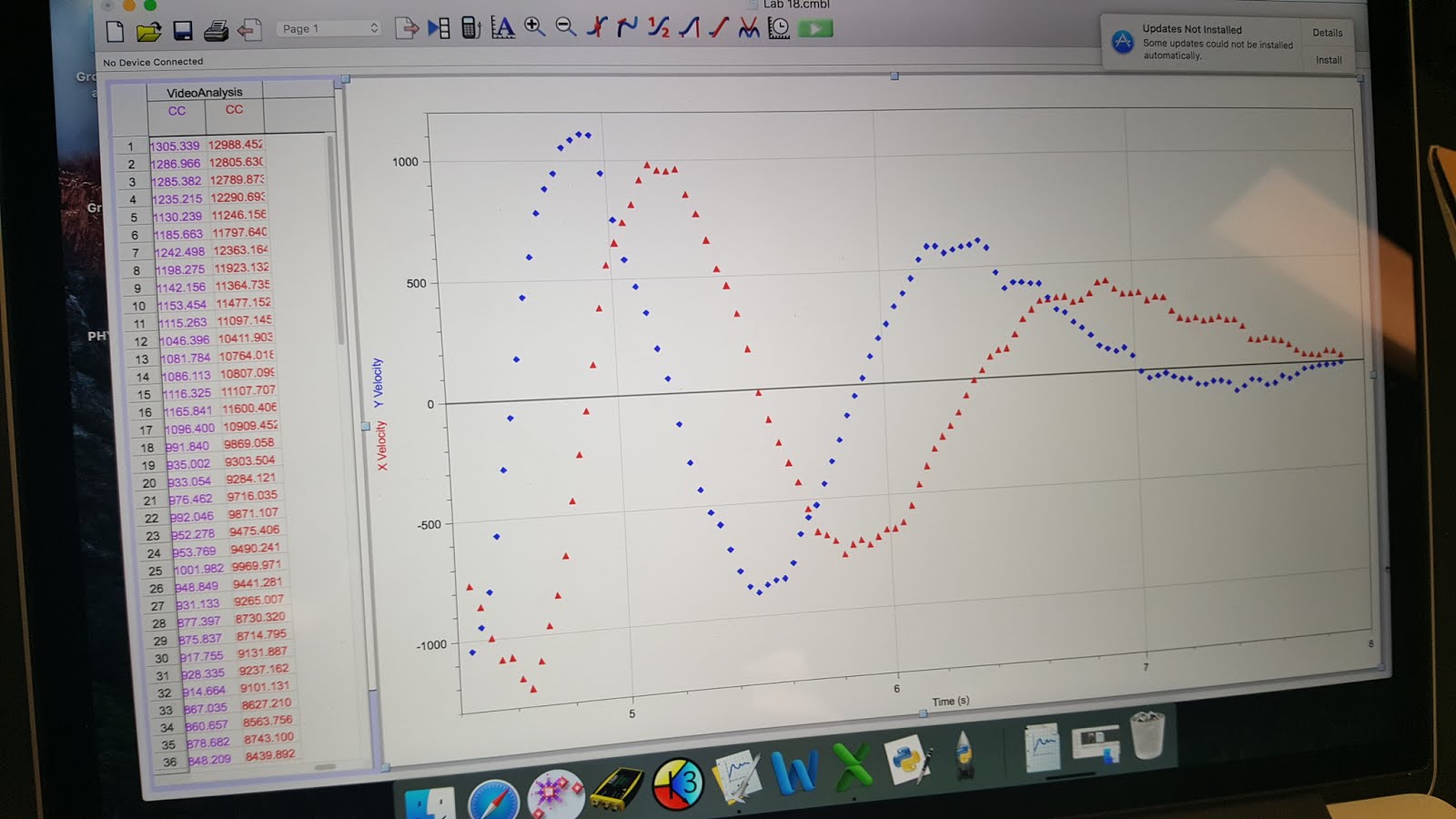
7) The graph first gives us the tangential velocity of the apparatus. So we use the formula to convert the tangential velocity to angular velocity and the radius of the metal disk. Then the results gives us a graph of the angular velocity and we use the slope as the results for angular acceleration for friction.
8) Now with these results giving us the values we need, we are ready to prove if our theoretical calculations match our experimental results. We chose forty degrees will be an appropriate value for the cart's motion. Let's begin on our theoretical calculations.
 Since the tension from the metal disk is the same tension pulling from the cart, we assume these two objects are being influenced by acceleration. We will focus on the metal disk first. The sum of torques the the metal disk is experiencing is the torque of the tension and the frictional torque. We then derived the tension of the metal disk.
Then we derived the tension from the cart. According the free body diagram, the acceleration the cart is experiencing is the tension from the string and some portion of force of gravity.
Now we let these tensions equations equal each other and derived the angular acceleration. Since the cart was experiencing tangential acceleration, we converted the tangential to angular acceleration and the radius. Now that we found the results for angular acceleration, we convert it back to tangential acceleration and solved for time using kinematics. Our results for time gave us roughly eleven seconds.
Now to prove our experiment will be similar to our theory, we inclined the ramp to forty degrees and made sure the tension is parallel to the cart. After giving three trials using a timer, here are our results.
 The average time gave us exactly the same results for our theoretical calculations!
No comments:
Post a Comment